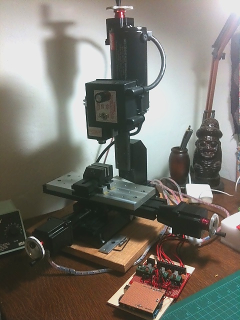
Designing a DIY CNC (for a Sherline Mill)
According to Machinist Mike, learning how your new machine responds to cutting metal is critical, because you can easily damage the mill, tool, or part, if you take it beyond its capabilities, like this overly-excited guy who probably ruined his very expensive mill spindle assembly by taking too aggressive cuts and using end mills in a drill chuck (a big no-no because of high lateral forces). Mike had recommended that I should use my mill manually, especially since I am relatively new to the act of cutting metal to make the parts, rather than designing them. Learning your machine also gives you an intuitive feel by hearing or seeing trouble before it happens, which can save your machine or your part during your CNC runs. After picking up my mill a few months back, I have been spending my time getting to know my mill by machining multi-use jigs, toe clamps, a tapping block, a tooling plate, and other handy tools that I will need in the future.
With the end goal of building a CNC mill, I opted for the CNC-ready version of the Sherline 5400 mill, which comes pre-installed with NEMA 23 stepper motor mounts, X-Y axis leadscrew oiler, more robust Z-axis leadscrew, adjustable “zero” handwheels, and preload bearings to remove end-play, anti-backlash features, and shaft motor couplers for all three axes. With a cost of only $250 more and the design quality, it was hard to argue to not get it. More time making, less time building.
The only minor issue is that the CNC-ready mill doesn’t include anything to mount the handwheels to the recessed shaft couplers, where they assume that you will be immediately installing a dual-shaft NEMA 23 stepper motor with the handwheels mounted onto the back-end. This is easy to bootstrap. All you need for each handwheel is a short section of 0.25″D steel rod with filed-down flats for the set screws that are long enough to span the recess and 1″ wide flat aluminum bar with 3 holes to span the diagonals of the stepper motor mounts with the middle hole providing some stability for the shaft and handwheel. Everything needed is available in a typical hardware store and can be made with basic hand tools.
One of the many nice things about Sherline mills is that they have a large selection of pre-built parts and mechanisms designed for their machines, including a fully capable CNC setup, complete with technical details. According to their website, their CNC-builds use an Allegro SLA7044M unipolar stepper driver with a 24V/4A power supply. Their motors are NEMA 23 with 1/4″ diameter dual shaft, 3.2V/2A, 120 oz-in torque rating, a 1.8deg (200 steps/rev), and 250 g-cm^3 rotor inertia (important for acceleration). Their maximum feedrate is 22 ipm, which may sound slow to some people, but most metal milling operations should occur below 6 ipm and the maximum travel in any direction is 9″. From this, these are the minimum design parameters I will be basing my build off of.
In choosing a stepper motor, the most significant force a CNC motor contends with is inertia from the motor rotors, leadscrews, mill table, etc. High inertial forces occur when starting, stopping or changing directions during an operation, which also governs how well your mill can machine tight curves due to centripetal acceleration. If your motor does not supply enough torque to overcome the inertial forces, the steppers will likely skip steps and lose track of its position, since the open-loop controller does not have any feedback to correct for this. In other words, high torque at cutting speeds (<6 ipm) is good.
Other factors to consider: Higher stepper driver voltage increases high speed motor torques and the maximum speed, but does not effect low-speed or holding torque. Higher driver current increases low-speed and holding torques but does not effect high-speed torque and the useable maximum speed. And, bipolar coil windings in series doubles low-speed torque but halves the maximum speed compared to when the coils are connected in parallel.
So, to get the most out of a stepper motor for a CNC application, a bi-polar stepper motor with coils wired in series, driven at the maximum rated current and highest allowable voltage, and a low rotor inertia should be used. If you are designing a DIY mill that is not a Sherline or do not have access to any technical information for a successful build, I would recommend to first compute how much inertia (rotational and translational) per axis of your machine and the torque required for your desired acceleration per axis. Since motor torque drops as speed increases, you will need to also determine the nominal torque due to friction in your machine to find the required torque at the maximum feedrate desired per axis. This should give you a baseline on what motor you will need.
From this, I ended up selecting a 2.2V/1.5A, 185 oz-in bi-polar stepper motor from Keling Inc for $27.95 each. They also supply another slightly smaller and lighter 6.1V/1.7A, 156 oz-in stepper that would work as well, but did not have as quite as nice of a torque vs. speed curve. Although the mass and rotor inertias of these stepper motors are slightly higher (0.6 vs 0.7 kg) than used in the Sherline CNCs, the torque is significantly greater, especially considering they are driven as bi-polar rather than uni-polar. It should provide slightly better acceleration response and less chance of skipping a step but mainly should drive the CNC at much faster maximum feedrates. A design trade that’s worth it in my mind.
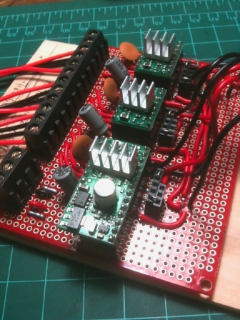
In choosing a bipolar stepper driver, there are many options, but for reasons in a previous post, I opted for Pololu’s A4983/A4988 bipolar stepper motor drivers. I had chosen these primarily due to their low-cost ($12.95 each), high-efficiency, simplicity, and high 2A maximum current per coil. (Sparkfun’s EasyDrivers do not supply enough current at 0.75A per coil.) With a simple circuit design, these should be able to interface via parallel port to EMC2 or any other CNC interface, as well as to an Arduino with grbl.
In choosing a power supply, the supply voltage should be just under the maximum voltage the drivers allow to allow for a little back EMF buffer. (Sorry ATX PC power supplies will not work here!) The Pololu stepper drivers have a maximum motor voltage of 32V and require heatsinks for currents over 1A per coil, but you don’t need much of one, if you drive the motors at the highest voltage possible. These drivers recycle the energy already present in the motor coils and tend to be more efficient with higher voltages. This is due to the high voltages forcing the energy out of the motor windings faster and ends up with less waste heat generated. Personally, I did see a huge difference in temperature between 24V to 30V. At 24V, the heatsinked drivers overheated within a minute at 1.5A per coil and tripped the internal thermal protection, and when at 30V, the driver heatsinks were hot, not searing, and didn’t require a fan. I had ended up purchasing a KL-150-24 24V/6.3A switching power supply from Keling for $39.95. These have a potentiometer to adjust the output DC voltage from the rated 24V by about +/- 6V, which provided me about 30V and probably up to 5A. Surprisingly, the Pololu stepper drivers are so efficient, when all three are active in full-step mode (all windings energized), the current drawn from the power supply is no more than 1A. As of yet, I have not exceeded the capabilities of the power supply, even under cutting load.
With everything selected, next came the build, which is very straight forward. I had first built everything on a breadboard to make sure the circuit was good. Just follow the wiring diagrams for the Pololu stepper drivers and here are a few things that I came across that should be noted here. Try to use decoupling capacitors to ensure a clean source of power for both the logic and motor power. Logic ground should be shared with all other logic grounds, including your controller. The motor power grounds should be star grounded at the motor power terminal. Logic and motor ground are already shared internally in each Pololu stepper driver board and do not need to an additional external connection between the two. (Fairly sure on this. This keeps the two grounds independent of each other and adding another ground at the star ground would likely cause a ground loop.) Finally, the Pololu A4983 stepper drivers need a pull-down resistor for the MS1 pin to operate correctly. Their other three stepper drivers have internal pull-down resistors for that pin. Not really sure why.
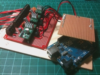
After the breadboard testing, I picked up a small protoboard from Sparkfun and built the circuit. I highly recommend getting a good plated protoboard. It will save you some soldering headaches for little cost. Also, I had created some DIY jumpers with some female headers and breadboard wire to easily change the microstep size for each driver and make the sleep and reset pins readily available for future mods. If you choose to use grbl, the pictured Arduino uses the grbl edge version 0.7b, not the current master 0.6b. This is due to a switch in how the stepper enable pin is held high/low between versions and the compatibility with the Pololu drivers and the grblshield too. To get grbl edge version 0.7b, hit the link, download and compile the source code, and flash it to your Arduino, all according to Simen’s instructions.
In testing the DIY CNC system, everything went exactly as planned, except for one thing. Steppers are driven with square wave pulses and create higher and higher audible frequencies when driven faster and faster. At high enough frequencies, they can excite the structural vibration modes of your mill, causing everything to shake and rattle. To minimize any resonance effects, you need to select a motor with low mass as in stated in a previous post. But, the one thing I didn’t account for is the vibration modes of the internal rotor of the motor. With the Keling steppers I had selected, if I were to 1/4 or 1/8 microstep at feedrates above 15 ipm, the motor internal rotor would begin to resonate and stall, even though it was no where near it’s maximum theoretical speed. In 1/2 microstep or full-step mode, the motor rotor wouldn’t resonate and run up to the motor’s maximum feedrate of 30-35 ipm (This corresponds to the torque curve when running up at 5kHz step pulses). So, I’m basically forced to run in half-stepping mode, which is just a bit louder in operation, but it’s plenty precise with steps equaling 0.000125″ per step and it’s still 50% faster than the Sherline CNC system. In hindsight, I would have selected a better quality stepper motor with a stiffer, more robust casing to remove the motor rotor resonance problem, but there was no way to tell if this would be a problem until I purchased and tested the motors anyhow.
So what’s next? At the moment, the DIY CNC system is streaming the grbl Arduino g-code commands through the USB serial port via a Python script and working as designed. I had intended to look into creating a headless system with joystick control and an LCD readout, but grbl is unfortunately still somewhat beta and isn’t designed for easily adapting an external interface to. Meaning, grbl does not currently have a way to get real-time feedback or issue real-time commands through its serial port interface. It also doesn’t have a way to compensate for backlash internally yet or some other useful features, such as variable feedrate, pause/reset, status reports, etc. Although it’s possible modify grbl to do these things, it still may not be the best solution for my mill, considering there is always EMC2. But, I do really like the idea of being able to write my own Python scripts to have complete control of the mill. Anyhow, I’m still looking into it and, depending on where its headed, considering in helping develop grbl, as it has a lot of promise, especially for other applications.
With this all said and done, this was a fun project and very cheap. The cost of a Sherline CNC driver-stepper only system is $805 ($1825 with computer with EMC2). With the cost of the motors (~$90), drivers (~$40), Arduino grbl controller (~$30), power supply ($40), and misc build hardware ($50), the total cost of a DIY build was roughly $250. Even though there is some more to do, like deciding on an enclosure and more proofing of the system, the DIY approach is, compared to the Sherline CNC, at least 33% the cost, 50% higher low-end torque, 50% higher maximum feedrate, and completely modular, maintainable, and cheap and easy to fix. Well worth the time, I say.


Great article! Any chance you can share your DIY shield? I recently had trouble with a grbl compatible shield I bought and am looking for another alternative. I still have my pololu drivers and figured that I can locate some capacitors too.
Thanks!
What I put together isn’t really a shield. I just took a standard PCB board and soldered some pins onto it. I had to bend some for the weird offset that the Arduino has, but it works pretty well. Which grbl shield did you have problems with?
I have the following motors from Sparkfun:
https://www.sparkfun.com/products/10847
I got them working with some TB6560 drivers.
I was using some small Pololu drivers with the Reactive Substance shield. I think I just needed more current than I had set the drivers to.
Any tips on how to get the proper GRBL settings? Right now their movement is not very smooth, there is a fair bit of vibration and the actual “stepping” is very noticeable.