Cleaning a Bicycle Chain

I ran across this link today and thought to myself, “Duh. Why don’t I do it this way?”
Cleaning a bike chain is the hands-down dirtiest task of maintaining a bike. Some bike shops will drop the dirty chains into an ultrasonic cleaner to get it nice and spiffy, but DIY’ers options are not so great. Shops sell special expensive chain cleaning tools that are expensive, prone to breaking, and don’t particularly work that well. They tend to spray dirty cleaning solution all over your bike and gears and cleaning the chain cleaner brushes is a task in itself.
Normally I would take off a bike chain (super easy with SRAM powerlink) and soak it a disposable tub, but that doesn’t get the difficult grease. This solution drops it into a large mouth bottle, where you can seal it and simulate a ultrasonic cleaner by just shaking the hell out of it. Flushing and staging with new cleaning solution will get your bike chain nice and clean.
Grbl: Proofing precision and accuracy
After building the DIY Sherline CNC, I had asked myself the question: “How do I proof the CNC/grbl to make sure that everything machines correctly and to spec?” I posed this question to my friend Machinist Mike, and he quickly responded: “Machine a diamond-circle-square test block!” and awesomely generated a g-code program for me to immediately use.

The diamond-circle-square test block is an old school method to machine a set of known shapes and dimensions to gauge the accuracy and precision of a CNC mill. The diamond gauges how well and straight the CNC tracks diagonal cuts; the circle gauges the circularity of the cuts; and the square gauges the primary axes and perpendicularity. This test also will show the effects from backlash, if your machine is not square, smooth feeds from the surface finishes, among other things. Today there are new and better methods to gauge the accuracy and precision of a CNC machine, as the link shows, but for DIY’ers, the diamond-circle-square test is a plenty robust enough test.
The exact sizes and depths of the shapes do not particularly matter, just as long as the user knows what they are. I would recommend to create a large enough test block that is about as large as the parts you intend to machine. A large shape will tell you if you have problems in a certain area of travel. For me, the Sherline has about a 5″ Y-axis travel and the test block was sized to be about 2″x2″ with shape depths of 0.1″.
Also, Mike had noted that when machining with a mill without rigid anti-backlash ball screws, one should always conventional cut, opposed to climb cut (unless doing a finishing pass.) This is because the cutting forces with a conventional cut always push against the leadscrews in the direction of cutting travel. Where as, with climb cutting, the cutting forces push away from the leadscrews in the direction of cutting, causing the axes motion to rattle between the length of the backlash. This can effect precision and surface finish, as well as prematurely wear your lead screws.
Anyhow, a couple of weekends ago, Machinist Mike and I ran the g-code program with the new changes to my grbl fork. We ensured the Sherline anti-backlash nuts were nice and tight with a backlash of less than 0.001″. (The higher torque of my DIY CNC build allowed me to tighten up the anti-backlash nuts more than I would have with the OEM CNC.) We ran the program without any problems from start to finish.
I’m very happy to report that the surface finishes were excellent, the circularity and perpendicularily were also excellent, and all measured dimensions are within <= 0.001″ of the design dimensions. Meaning that grbl and the DIY Sherline CNC are good to go!
Improving Grbl: Cornering Algorithm
Greasing the axle and pumping up the tires… on the metaphoric grbl wheel that is. I had spent some time to really understand the grbl source code these past few weeks, getting knee deep into the intricacies of it. More I had looked at it, the more I became impressed with Simen’s coding efficiency, showing what the little Arduino can do. In short, it can do a lot and still has plenty of room to grow. While grbl is still in development, I decided to take some initiative to help out and solve some problems still existing in the code, i.e. strange cornering behavior, full arc support with acceleration planning, and intermittent strange deceleration issues. As a researcher, I’m pretty much bound to document just about everything, even if it’s pretty insignificant. So here goes on part one.
The Cornering Algorithm: G-code motions involve piecewise linear movements, where each junction between these linear movements immediately turns and continues on to the next linear movement. The problem is that these junctions create problems with real-world CNC machines, since they can’t do these immediate and instantaneous changes in direction. Stepper motors have only a finite amount of torque and the high inertial forces required to make these quick direction changes can cause them to lose steps. The reason why this is so important is that stepper motor-based CNCs are open-loop control and have no feedback on what the motors are doing. A motor driver just knows that it received a step pulse and tries to move the motor. If it misses a step, the controller (grbl) has no idea and will lose its true position, resulting in a ruined part.
Simen had spent some time working on the problem of how to optimally solve for maximum junction speeds, such that to not exceed the maximum allowable acceleration limit of the machine. His approach is based on the euclidean norm of the entry and exit velocity vectors at the junction and limiting the maximum instantaneous change in velocity at the junction: 

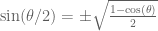
To come up with more robust solution of this problem, it needs to be both accurate for all ranges of motion and just as computationally efficient. After some thought, here’s what I came up with: First let’s assume that at a junction of two line segments, we only look at centripetal acceleration to simply things. In other words, we assume the tangential velocity is zero and the velocity through it is constant. At the junction, let’s place a circle with a radius 


This circular segment creates a virtual deviation from the path 
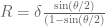
An efficient computation of the circle radius is as follows. If you do the geometry in terms of the known variables, you get: 


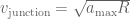
Now just plug and chug these equations into the centripetal acceleration equation above. You’ll see that there are only two sqrt() computations per junction and absolutely no trig sin() or acos(). To then find the absolute maximum velocity through the junction, just apply: 
This approach is both computationally efficient and accounts for the junction nonlinearities of how sharp the angle is between line segments and how fast the CNC can travel through each junction. Meaning that for right angles or reversing, the computed maximum junction speed is at or near zero. For nearly straight junctions, the computed maximum junction speed is near or at the nominal feedrates, which mean it can fly through the junction without worrying about exceeding the acceleration limits. This has been successfully tested on my machine and by several very helpful users, who have reported that they can crank up the feed speeds of their machines and it runs much smoother through complex paths. Lastly, keep in mind this method is a virtual path deviation that is only used for robustly computing the junction speed and does not actually mean there is a physical path deviation in your CNC machine.
Grbl: A Simple Python Interface
For people who are more Python inclined, here’s a stripped-down, simple streaming interface with grbl from your computer. The script will send single line g-code blocks to grbl and wait for an acknowledgement. Grbl will send an acknowledgement only when it’s done processing the block and has room in the buffer. So, when starting up, you should see it fly through the first 16 or so (328p Arduinos) commands quickly as the buffer fills, and then it should steadily stream more commands as grbl completes blocks. I can only give setup details for Macs, but this script should work on just about any operating system with an up-to-date version of Python and the same general steps are followed.
For Macs, there are only a few things you will need to do to get up and running. Python, by default, is already installed, but you will need the PySerial library to interface with the Arduino. To install, simply run the Terminal.app and type sudo easy_install pyserial at the prompt.
You will also need to find the device path for your Arduino connected to your USB port. At the Terminal.app prompt, just type ‘/dev/tty.usbmodem’ and hit tab one or two times. This should come up with short list of device ports that is your Arduino. It will likely just come up with one. Replace the complete path in the script, along with the filename of your g-code. (Note: Arduino paths can change if you plug into a different port later)
To run, you can either use ‘python stream.py’ (or whatever you will call this Python script) or set the permissions to execute the script by filename.
That’s it!
#!/usr/bin/env python
"""\
Simple g-code streaming script for grbl
"""

import serial
import time

# Open grbl serial port
s = serial.Serial('/dev/tty.usbmodem0000',9600)

# Open g-code file
f = open('somefile.gcode','r');

# Wake up grbl
s.write("\r\n\r\n")
time.sleep(2)   # Wait for grbl to initialize
s.flushInput()  # Flush startup text in serial input

# Stream g-code to grbl
for line in f:
    l = line.strip() # Strip all EOL characters for streaming
    print 'Sending: ' + l,
    s.write(l + '\n') # Send g-code block to grbl
    grbl_out = s.readline() # Wait for grbl response with carriage return
    print ' : ' + grbl_out.strip()

# Wait here until grbl is finished to close serial port and file.
raw_input("  Press <Enter> to exit and disable grbl.")

# Close file and serial port
f.close()
s.close()
NOTE: For more advanced stuff, you can take advantage of the 128 character serial buffer on the Arduino and design the script to keep careful track of how many characters you have sent and how many have been processed by each ‘ok’ response. If you ever run into any data starving problems (by using a wickedly slow computer like my resurrected 550Mhz Powerbook G4), this creates another buffer layer and provides grbl immediate access to g-code commands without having to wait for any serial processes. So far, it has worked very well for me when having to send a long series of very short line segments.
Grbl: How it works and other thoughts…
While grbl is a fantastically simple and economical g-code interpreter and CNC stepper motor controller for the Arduino, there doesn’t seem to be much information on how an average or new Arduino user should interface with it or how it works internally. So, here’s a shot at filling that gap.
(As of this writing, grbl versions are master 0.6b and edge 0.7b)
The first thing that people should know about grbl is that its designed to be simple and barebones. It is not a complete solution for all CNC milling, but it is rather it seems to be intended as a starting point for anyone building a 3-axis cartesian-type mill, router, laser cutter, 3d printer, etc. It started as a stripped down and general-use port of the Reprap Arduino GCode Interpreter, which is more geared for 3d printing only.
Grbl works primarily through the Arduino serial port interface and needs a constant stream of g-code commands sent via a computer or some other means. Grbl accepts and processes single g-code blocks followed by a carriage return, ignoring gcode comments and block delete characters. It returns an ‘ok’ or ‘error:X’ message when it has processed the block and is ready for more information. A simple ruby script for g-code streaming is supplied in the code base for reference. Python scripts also work very well for streaming grbl g-code, but ultimately it’s up to the user in how to interface with it.
To get an idea how grbl works internally, there are essentially two programs running concurrently on grbl. The main program reads the serial port for g-code commands, parses them, then passes it to an acceleration/feedrate planner, and finally places the event into a ring buffer (max 5 blocks for 168 and 16 blocks for 328p Arduinos.) The other program is interrupt driven and works in the background. It controls the stepper motors and sends step pulses and direction bits to the stepper driver pins. It sequentially processes through the ring buffer events, FIFO-style, until it is empty.
For most part, the main program will continually accept new gcode blocks as quickly as it can be processed as long as there is room in the buffer. If the buffer is full, the grbl will not send a response until the interrupt program has finished an event and cleared it from the buffer. For streaming, this means the user interface should always wait for an ‘ok’ or ‘error’ response from grbl before sending a new g-code block. Also, the data stream should be steady and uninterrupted to minimize the chance of ‘data starving’ grbl, aka emptying the buffer, which will cause unintended hiccups in the CNC movements.
As for external interfaces, there are only XYZ limit switches. Other features, such as pause/halt, variable speed reductions for proofing, homing cycles, real-time jogging or manual interface, are currently not supported or are in-development. It should be noted that some of these features are left to the user to decide to add, mainly to stay with the vision of simplicity and portability. Canned cycles and tool radius compensation/offsets are not supported, but this may be handled by an external preprocessor that has yet to be written. Also, there is currently no protocol in querying or broadcasting the current status of grbl, as in the size of the ring buffer, distance to go on current block, and current position.
For all the cool stuff that grbl can do, there are also still some bugs that are being ironed out. G02/03 arcs are not supported by the acceleration planner and intentionally forces the ring buffer to empty, causing some short motion hiccups when the main program has to process a new g-code block to fill the ring buffer and weird accelerations coming into and out of an arc. Although, there has been a lot development here to solve this problem recently and should be ironed out soon. The same could be said of the acceleration planner itself in terms of improving speed and robustness. G04 dwelling forces the ring buffer to empty as well, but doesn’t really pose too much of an issue other than having to re-fill an empty buffer upon resuming.
Regardless of its minor ‘issues’, grbl has a lot of potential and creates a wonderful and economical introduction to a large potential audience of makers and DIYers into the world of CNC. Even then, the possibilities for other applications, such as expanding to 6-axis hexapods or robotics, are very exciting. Anyhow, for about 95% of things that any home user would want to do with grbl, it will work as is. For the other 5%, like precision machining or production, there is still a ways to go, but it’s getting there.
UPDATE: Here’s a list of currently supported g-code commands and unsupported commands from grbl gcode.c
- G0, G1 – Seek and linear motion with acceleration planning
- G2, G3 – CW and CCW arc motions with no acceleration planning
- G4 – Dwell (Up to 6 seconds, for now)
- G17, G18, G19 – Plane select
- G20, G21 – Inches mode enable and disable
- G53, G90, G91 – Absolute mode override, enable, and disable
- G80 – Motion mode cancel
- G92 – Coordinate offset
- G93, G94 – Inverse feedrate mode enable and disable
- M3, M4 – Spindle direction
- (TBD) M0, M1, M2, M30, M60 – Program pause and completed
- (TBD) M5 – Spindle speed
- (TBD) G28, G30 – Go home
- Intentionally not supported: Canned cycles, Tool radius compensation, ABC-axes, Multiple coordinate systems/home locations, Evaluations of expressions, Variables, Probing, Override Control, Non-modal G-codes (G10,G28,G30,G92,G92.1,G92.2,G92.3), Coolant (M7,M8,M9), Overrides (M48,M49), Coordinate system selection, and path mode control.
Designing a DIY CNC (for a Sherline Mill)

According to Machinist Mike, learning how your new machine responds to cutting metal is critical, because you can easily damage the mill, tool, or part, if you take it beyond its capabilities, like this overly-excited guy who probably ruined his very expensive mill spindle assembly by taking too aggressive cuts and using end mills in a drill chuck (a big no-no because of high lateral forces). Mike had recommended that I should use my mill manually, especially since I am relatively new to the act of cutting metal to make the parts, rather than designing them. Learning your machine also gives you an intuitive feel by hearing or seeing trouble before it happens, which can save your machine or your part during your CNC runs. After picking up my mill a few months back, I have been spending my time getting to know my mill by machining multi-use jigs, toe clamps, a tapping block, a tooling plate, and other handy tools that I will need in the future.
With the end goal of building a CNC mill, I opted for the CNC-ready version of the Sherline 5400 mill, which comes pre-installed with NEMA 23 stepper motor mounts, X-Y axis leadscrew oiler, more robust Z-axis leadscrew, adjustable “zero” handwheels, and preload bearings to remove end-play, anti-backlash features, and shaft motor couplers for all three axes. With a cost of only $250 more and the design quality, it was hard to argue to not get it. More time making, less time building.
The only minor issue is that the CNC-ready mill doesn’t include anything to mount the handwheels to the recessed shaft couplers, where they assume that you will be immediately installing a dual-shaft NEMA 23 stepper motor with the handwheels mounted onto the back-end. This is easy to bootstrap. All you need for each handwheel is a short section of 0.25″D steel rod with filed-down flats for the set screws that are long enough to span the recess and 1″ wide flat aluminum bar with 3 holes to span the diagonals of the stepper motor mounts with the middle hole providing some stability for the shaft and handwheel. Everything needed is available in a typical hardware store and can be made with basic hand tools.

One of the many nice things about Sherline mills is that they have a large selection of pre-built parts and mechanisms designed for their machines, including a fully capable CNC setup, complete with technical details. According to their website, their CNC-builds use an Allegro SLA7044M unipolar stepper driver with a 24V/4A power supply. Their motors are NEMA 23 with 1/4″ diameter dual shaft, 3.2V/2A, 120 oz-in torque rating, a 1.8deg (200 steps/rev), and 250 g-cm^3 rotor inertia (important for acceleration). Their maximum feedrate is 22 ipm, which may sound slow to some people, but most metal milling operations should occur below 6 ipm and the maximum travel in any direction is 9″. From this, these are the minimum design parameters I will be basing my build off of.
In choosing a stepper motor, the most significant force a CNC motor contends with is inertia from the motor rotors, leadscrews, mill table, etc. High inertial forces occur when starting, stopping or changing directions during an operation, which also governs how well your mill can machine tight curves due to centripetal acceleration. If your motor does not supply enough torque to overcome the inertial forces, the steppers will likely skip steps and lose track of its position, since the open-loop controller does not have any feedback to correct for this. In other words, high torque at cutting speeds (<6 ipm) is good.
Other factors to consider: Higher stepper driver voltage increases high speed motor torques and the maximum speed, but does not effect low-speed or holding torque. Higher driver current increases low-speed and holding torques but does not effect high-speed torque and the useable maximum speed. And, bipolar coil windings in series doubles low-speed torque but halves the maximum speed compared to when the coils are connected in parallel.
So, to get the most out of a stepper motor for a CNC application, a bi-polar stepper motor with coils wired in series, driven at the maximum rated current and highest allowable voltage, and a low rotor inertia should be used. If you are designing a DIY mill that is not a Sherline or do not have access to any technical information for a successful build, I would recommend to first compute how much inertia (rotational and translational) per axis of your machine and the torque required for your desired acceleration per axis. Since motor torque drops as speed increases, you will need to also determine the nominal torque due to friction in your machine to find the required torque at the maximum feedrate desired per axis. This should give you a baseline on what motor you will need.
From this, I ended up selecting a 2.2V/1.5A, 185 oz-in bi-polar stepper motor from Keling Inc for $27.95 each. They also supply another slightly smaller and lighter 6.1V/1.7A, 156 oz-in stepper that would work as well, but did not have as quite as nice of a torque vs. speed curve. Although the mass and rotor inertias of these stepper motors are slightly higher (0.6 vs 0.7 kg) than used in the Sherline CNCs, the torque is significantly greater, especially considering they are driven as bi-polar rather than uni-polar. It should provide slightly better acceleration response and less chance of skipping a step but mainly should drive the CNC at much faster maximum feedrates. A design trade that’s worth it in my mind.
In choosing a bipolar stepper driver, there are many options, but for reasons in a previous post, I opted for Pololu’s A4983/A4988 bipolar stepper motor drivers. I had chosen these primarily due to their low-cost ($12.95 each), high-efficiency, simplicity, and high 2A maximum current per coil. (Sparkfun’s EasyDrivers do not supply enough current at 0.75A per coil.) With a simple circuit design, these should be able to interface via parallel port to EMC2 or any other CNC interface, as well as to an Arduino with grbl.
In choosing a power supply, the supply voltage should be just under the maximum voltage the drivers allow to allow for a little back EMF buffer. (Sorry ATX PC power supplies will not work here!) The Pololu stepper drivers have a maximum motor voltage of 32V and require heatsinks for currents over 1A per coil, but you don’t need much of one, if you drive the motors at the highest voltage possible. These drivers recycle the energy already present in the motor coils and tend to be more efficient with higher voltages. This is due to the high voltages forcing the energy out of the motor windings faster and ends up with less waste heat generated. Personally, I did see a huge difference in temperature between 24V to 30V. At 24V, the heatsinked drivers overheated within a minute at 1.5A per coil and tripped the internal thermal protection, and when at 30V, the driver heatsinks were hot, not searing, and didn’t require a fan. I had ended up purchasing a KL-150-24 24V/6.3A switching power supply from Keling for $39.95. These have a potentiometer to adjust the output DC voltage from the rated 24V by about +/- 6V, which provided me about 30V and probably up to 5A. Surprisingly, the Pololu stepper drivers are so efficient, when all three are active in full-step mode (all windings energized), the current drawn from the power supply is no more than 1A. As of yet, I have not exceeded the capabilities of the power supply, even under cutting load.

With everything selected, next came the build, which is very straight forward. I had first built everything on a breadboard to make sure the circuit was good. Just follow the wiring diagrams for the Pololu stepper drivers and here are a few things that I came across that should be noted here. Try to use decoupling capacitors to ensure a clean source of power for both the logic and motor power. Logic ground should be shared with all other logic grounds, including your controller. The motor power grounds should be star grounded at the motor power terminal. Logic and motor ground are already shared internally in each Pololu stepper driver board and do not need to an additional external connection between the two. (Fairly sure on this. This keeps the two grounds independent of each other and adding another ground at the star ground would likely cause a ground loop.) Finally, the Pololu A4983 stepper drivers need a pull-down resistor for the MS1 pin to operate correctly. Their other three stepper drivers have internal pull-down resistors for that pin. Not really sure why.

After the breadboard testing, I picked up a small protoboard from Sparkfun and built the circuit. I highly recommend getting a good plated protoboard. It will save you some soldering headaches for little cost. Also, I had created some DIY jumpers with some female headers and breadboard wire to easily change the microstep size for each driver and make the sleep and reset pins readily available for future mods. If you choose to use grbl, the pictured Arduino uses the grbl edge version 0.7b, not the current master 0.6b. This is due to a switch in how the stepper enable pin is held high/low between versions and the compatibility with the Pololu drivers and the grblshield too. To get grbl edge version 0.7b, hit the link, download and compile the source code, and flash it to your Arduino, all according to Simen’s instructions.
In testing the DIY CNC system, everything went exactly as planned, except for one thing. Steppers are driven with square wave pulses and create higher and higher audible frequencies when driven faster and faster. At high enough frequencies, they can excite the structural vibration modes of your mill, causing everything to shake and rattle. To minimize any resonance effects, you need to select a motor with low mass as in stated in a previous post. But, the one thing I didn’t account for is the vibration modes of the internal rotor of the motor. With the Keling steppers I had selected, if I were to 1/4 or 1/8 microstep at feedrates above 15 ipm, the motor internal rotor would begin to resonate and stall, even though it was no where near it’s maximum theoretical speed. In 1/2 microstep or full-step mode, the motor rotor wouldn’t resonate and run up to the motor’s maximum feedrate of 30-35 ipm (This corresponds to the torque curve when running up at 5kHz step pulses). So, I’m basically forced to run in half-stepping mode, which is just a bit louder in operation, but it’s plenty precise with steps equaling 0.000125″ per step and it’s still 50% faster than the Sherline CNC system. In hindsight, I would have selected a better quality stepper motor with a stiffer, more robust casing to remove the motor rotor resonance problem, but there was no way to tell if this would be a problem until I purchased and tested the motors anyhow.
So what’s next? At the moment, the DIY CNC system is streaming the grbl Arduino g-code commands through the USB serial port via a Python script and working as designed. I had intended to look into creating a headless system with joystick control and an LCD readout, but grbl is unfortunately still somewhat beta and isn’t designed for easily adapting an external interface to. Meaning, grbl does not currently have a way to get real-time feedback or issue real-time commands through its serial port interface. It also doesn’t have a way to compensate for backlash internally yet or some other useful features, such as variable feedrate, pause/reset, status reports, etc. Although it’s possible modify grbl to do these things, it still may not be the best solution for my mill, considering there is always EMC2. But, I do really like the idea of being able to write my own Python scripts to have complete control of the mill. Anyhow, I’m still looking into it and, depending on where its headed, considering in helping develop grbl, as it has a lot of promise, especially for other applications.
With this all said and done, this was a fun project and very cheap. The cost of a Sherline CNC driver-stepper only system is $805 ($1825 with computer with EMC2). With the cost of the motors (~$90), drivers (~$40), Arduino grbl controller (~$30), power supply ($40), and misc build hardware ($50), the total cost of a DIY build was roughly $250. Even though there is some more to do, like deciding on an enclosure and more proofing of the system, the DIY approach is, compared to the Sherline CNC, at least 33% the cost, 50% higher low-end torque, 50% higher maximum feedrate, and completely modular, maintainable, and cheap and easy to fix. Well worth the time, I say.
Grbl: Why reinvent the wheel?
Recently, I took a stab at trying to write a stepper motor driver for an Arduino, mainly to see what it would entail to get precise control for all three axes of the CNC and do other tasks as well. I have seen a lot of short example Arduino programs around online to do this, but usually only for one motor. To my surprise (or not), creating three, asynchronous pulse trains for the stepper motors, while simultaneously making the necessary computations for each block of g-code, was a bit more difficult to do, mainly due to the processing limitations of the Arduino. This is especially a problem if you want to anything else on top of this, like an LCD display, joystick manual control, etc.
To create precisely timed, asynchronous pulse trains requires interrupt programming, where you commandeer one or both of the PWM timers in the Arduino to use as an internal clock, independent of the main clock, to time the pulses. Interrupt programming basically counts down from a user-specified time and when reaching zero: pauses the main program, runs the interrupt code, which in this case is a single stepper pulse, then resumes the main program. But, along with being more difficult to program for, the main drawback is the more interrupts you have, the slower the main code runs.
For my Sherline DIY CNC, the frequency of the interrupt pulse trains can cause a problem. Suppose we look at the worst case scenario and we set the maximum feedrate to 20 inch/min for all three axes. With a 20 threads/inch leadscrew and 200 steps/rev stepper motor in full step mode, each stepper control pulses require a rate of 20*20*200/60 = 1333.3 step/sec. Not too bad. But, if we’d like to microstep the stepper motors at 1/4 steps, each stepper pulse rate goes up to 4 pulse/step * 1333.3 step/sec = 5333.3 pulse/sec. That’s 5.3 kHz… for one motor. All together, the Arduino needs to supply an asynchronous pulse train to all three motors at rate of roughly 16 kHz, or every 63 microseconds.
So, now the question is how much processing time is there left to still run the main program to load, interpret, and execute the next g-code block and other tasks. In short, not much. Allegro-based stepper motor drivers have a minimum 1 microsecond pulse rise and fall to process and read a step has occurred. So, let’s set a relatively conservative pulse total time at 15 microseconds to ensure the pulse is received, and the interrupt program has a 5 microsecond overhead. This leaves about 43 microseconds between pulses for the main program to run. Given that the Arduino runs at 16MHz (16 CPU cycles per microsecond), the main program will only go through very short segments of program execution and will effectively run at most 68% of normal speed. If you decide to microstep at 1/8 step, things go from bad to worse, where the main program will run at most 37.5% speed (under the same assumptions). Additionally, this is assuming that internal interrupt handling during runtime is 100% efficient, which is likely not the case.
Although this is only a worst-case scenario, this just shows how the Arduino has the potential of struggling to multi-task with high-frequency pulse trains and other desired tasks in certain situations. If the Arduino can’t keep up, what will likely happen is stalling during CNC operation between g-code blocks, motor jitter which can lead to skipped steps due to rapid stops and accelerations, or the Arduino itself crashing and not finishing the job, where you then have to figure out how to reset your g-code to start in a middle of the program while likely having lost your reference point. This is not good for you, on the part or the tool, let alone finish of a machined part (a stall causes the cutting tool to dwell, leaving unsightly tool marks).
So, where does this leave me? Sure, it’s very possible to write code that will do everything that I’d like an Arduino to do. Sure, if the steppers jitter, it might not be that bad. BUT, just looking at this interrupt issue makes me cringe at the thought of how much time programming and testing and programming and debugging and programming and etc,etc. will be involved in making sure the code is solid and dependable. Plus, with the great possibility that the Arduino compilers doesn’t optimize well, it will likely have be written in a traditional programming language, as in C++. But, luckily somebody already has. Thank you, Simen!
Grbl (github,blog), written by Simen S.S. of Norway, is an open-source g-code interpreter for driving stepper motors on standard 328 Arduinos. It’s written in C to create a highly optimized, efficient, stable controller capable of independently driving 3 stepper motors, for up to 30k (according to site) jitter-free step pulses. It’s well-tested, handles acceleration and deceleration, queues up to 20 g-code blocks, and even with a planner to anticipate and execute efficient movements.
Although the code itself is beautifully written and well commented, there isn’t much information yet on how it works and how to interface with it for those of you that can’t read C code. In my next post, I’ll take a shot at it for the rest of us out there.
For me, grbl is simple and nearly the perfect solution, but can be difficult to implement into my CNC system, if I want to modify the code for my own personal changes, i.e. head-less control, manual control via joystick, adjusting feedrates, LCD display with read-outs on position, read-write SD-card with g-code, etc. Meaning that for every new release, the new code must be re-modified for each of my personal changes and then thoroughly re-proofed that it did not screw up the performance of motor pulse trains. Not to mention, this must all be written in C as well, since Simen’s code cannot be efficiently translated to Arduino language. Rather than deal with this, I like Ed’s two controller solution (Ed’s Life Daily), where he uses one ‘slave’ grbl Arduino dedicated to g-code and motor control and another ‘master’ Arduino for reading an SD-card and streaming the ‘slave’ the g-code commands. This keeps grbl and the user interface independent of each other and resistant to any other new features that Simen decides to add in the future. But, rather than just streaming code, you could program the ‘master’ Arduino in the simpler Arduino environment using their standard libraries to just perform the majority of tasks that you would want headlessly, which, IMO is an order of magnitude easier and simplier to program and maintain.
As the post title states, why reinvent the wheel?
UPDATE: First, let me say that the conclusions of this post need some clarification. A little over a year since I wrote this post, much has happened, such as becoming a main developer for Grbl, and I have learned quite a lot. When this was written, I came from a background of interpreted programming languages, like Matlab and Python, where programs run much like scripts, direct and linear, with little to no multitasking. The same could be said with the Arduino IDE in the way its designed to work easily for beginning users. The point is that, even though an Arduino and other microcontrollers can easily perform high frequency stepper pulses, a fully functioning and reliable CNC controller requires advanced algorithms and techniques to account for how to handle everything else, such as the incoming serial data stream, parsing the data, planning the accelerations (which you have to do with the open-loop control of the steppers), and add any other features like real-time status reports and control switches. If the controller either can’t keep a steady stream of stepper pulses or can’t keep up with feeding the steppers the correct motions, the steppers will likely lose steps (hence position) and crash into something. One of the many of Grbl’s tricks to solve the problem described in this post is by combining all of the different axes stepper pulses with a Bresenham line algorithm into one stepper pulse ‘tick’, rather than three different ones, and manage the memory and data flow very efficiently. As a part of Grbl, we’re constantly pushing the limits of what the little Arduino can do and adding more features all the time. If you’d like to learn more, contribute, or would like to see a new feature added to Grbl, please visit us at Github.
Virtues of Rapid Prototyping and Strandbeests

STRANDBEESTS: If you don’t know Theo Jansen, he is an eclectic Dutch kinetic sculptor and physicist, who creates moving works of engineering and art that are hypnotically elaborate. These Strandbeests are designed to be easily moved by a light wind and can be typically found roaming the windy beaches of the Netherlands. These works are laboriously hand-constructed with electrical PVC tube, plywood, and other materials. When you see how freely and effortlessly his works move, you gain a supreme appreciation of how science can be applied into creating kinetic beauty. Here’s a video from TED a few years ago of the artist himself describing his work.
A short while ago, I had told a friend that rapid-prototyping is a toy and isn’t ready for prime-time, since the typical materials have it uses has poor mechanical properties. I’ve been quite a skeptic, but recently, I have had the luxury of having access to an industrial rapid-prototyping machine and have been trying to think of way to use it in a productive way. After using it and understanding the utility of them, I am beginning to believe…
With traditional machining, one of the most difficult things about mechanical design is figuring out how to make your parts machinable. In other words, can you make a square hole or square interior corner with a mill or lathe? Realistically, no. Or, how can I get the mill tool into the right area to remove material? Is the tool long or stiff enough? Can you make something hollow? You’d be surprised how many times you would come across problems like these in designing something complicated. Rapid prototyping can solve many of these problems, since the process doesn’t care how complicated a part is or how many features there are. But this isn’t to say that this is the end-all-be-all solution. It has it’s limitations as well: non-precision surfaces, less material strength, minimum thicknesses, and certain types of objects are unprintable, i.e. non-self-supported/floating or thin/wiry objects.
The most straightforward and obvious application of rapid prototyping is being able to physically play with and quickly test an idea, no matter how complicated the part. You take an idea, model it, print it, and it’s in your hands in less than a day. In stark contrast, machining a complicated part out of a solid block of metal can take days or more than week, mainly for planning and fixturing, depending on the number of features. Suppose you forgot to add a feature or sized the part wrong, just add it or scale it up, print it, and you’re done. With machining, you adjust your CNC code, if you’re so lucky, and re-machine a new part, which still can take a whole day or more.
But, probably the single-most greatest strength of rapid prototyping is that it doesn’t care how many parts you want to make or how different they are. You can design hundreds of small parts that all different, send it to the machine, and it will create them all, likely in one run. Just try asking a machine shop to do that in a day… (Sorry Mike!)

Theo Jansen applied these strengths to rapidly create small models of his Strandbeests in one step, which simplified his process incredibly. To create something like this in the traditional machine shop methods or even injection molding or casting, it would take as much time and effort as building a full size one out of his typical electrical tubing or wood. Here, the utility and the virtues of rapid prototyping can be fully realized.
While there are many types of rapid-prototyping methods, many of these machines are outside the reach of the home hobbyist since they can require expensive materials, as in powdered titanium alloys, and high powered equipment, as in lasers that not only can make you blind, but can also burn a hole through your eyeball. With these machines, you can easily create high resolution, accurate (around +/- 1mm), strong-ish parts (about half the strength and stiffness of traditional materials), made from high strength plastics like nylon, aluminum or glass-bead impregnated plastics, or even fused steel or titanium alloys. These machines are usually reserved for industry and professionals, but Shapeways provides this service for everyone at a reasonable cost, charging by the cubic centimeter. Just upload a solid model, pick the material (even stainless-steel), wait a week or so, and you got your part! Not exactly rapid, but better than nothing!
If you’d like your own at home, the popular open-source Reprap project is great place to start, but has limited capabilities. The project revolves around the idea of creating a ‘self-replicating’ machine, which currently lays melted, extruded plastic much like a hot-glue gun in a controlled CNC fashion. The objects it can create are like what you would expect, like they were made with a hot-glue gun, except a little harder and stronger. Great to screw around with, but the parts don’t have much mechanical utility since they are relatively soft and non-uniform, meaning that you wouldn’t want to use it for anything that would be under any type of force… at least not yet. Development and popularity of the project is high and I’m personally excited to see where it goes from here.
‘Frog-Leg’ Indicator Holder

D’oh! I forgot to buy an indicator holder when I did my last mass tool purchase. Rather than trying to track down a decent, cheap one in town (not likely here in NM) or order one and wait for a week, I built one. After talking with Machinist Mike, a ‘frog-leg’ type indicator holder would probably be the simplest and most useful, since it can articulate into just about any position. The shown design is made for a dial indicator, but another end ‘leg’ can be made to attach anything else, like a test indicator.
For material, all you need is 3/8″ aluminum round, which you can find at any hardware store. For screws, you need two 10-32, 0.5″ socket head cap screws and a 1/4-28, 0.5″ button head cap screw. I used a button head for the dial indicator mount, since it uses the same hex wrench as the 10-32. The threading placement may seem funky, but I did it so that all the bolts are facing the same direction when assembled.
Also, the milling process is designed to be easy. After cutting the round stock to length, each leg can be machined in one operation: clamp it high in the vice with a 5/8″ parallel, face the top features with an end mill, and drill the holes. Since you are measuring from the spindle to the indicator, the indicator holder doesn’t have be precise, but, by facing and drilling all of the mating faces of the parts in one step, you can ensure the movement of the legs are in-plane with the spindle axis.
Lastly, if the root ‘leg’ doesn’t fit into the 3/8″ end mill tool holder, just use some fine grit sandpaper to lightly sand down to spec.

A Small Tapping Block

A few days ago, I mentioned to Machinist Mike about tapping a ton of holes in a tooling plate I have been planning on making. He showed me this great little tapping block he made and regularly uses. It was made of 2 inch steel round with 9 holes for #0 to 1/2″ taps, which acts as guides to keep the tap perpendicular to the surface of the part. He graciously gave me a copy of his solid model to build my own.
I built a smaller version with some scrap aluminum I had laying around. It has 5 holes for #0 to 1/4″ taps, which should cover 95% of tapping on projects with a Sherline or a benchtop mill. If I need bigger, I could always make another one. If you’d like to make your own, the drawing is shown below. Measurements are referenced from the smallest hole.
UPDATE: To get into some tighter spots, the drawing now shows all of the guide holes closer to the outer edge of the block, but still with enough meat to hold up well for a while.

