Archive
Improving Grbl: Cornering Algorithm
Greasing the axle and pumping up the tires… on the metaphoric grbl wheel that is. I had spent some time to really understand the grbl source code these past few weeks, getting knee deep into the intricacies of it. More I had looked at it, the more I became impressed with Simen’s coding efficiency, showing what the little Arduino can do. In short, it can do a lot and still has plenty of room to grow. While grbl is still in development, I decided to take some initiative to help out and solve some problems still existing in the code, i.e. strange cornering behavior, full arc support with acceleration planning, and intermittent strange deceleration issues. As a researcher, I’m pretty much bound to document just about everything, even if it’s pretty insignificant. So here goes on part one.
The Cornering Algorithm: G-code motions involve piecewise linear movements, where each junction between these linear movements immediately turns and continues on to the next linear movement. The problem is that these junctions create problems with real-world CNC machines, since they can’t do these immediate and instantaneous changes in direction. Stepper motors have only a finite amount of torque and the high inertial forces required to make these quick direction changes can cause them to lose steps. The reason why this is so important is that stepper motor-based CNCs are open-loop control and have no feedback on what the motors are doing. A motor driver just knows that it received a step pulse and tries to move the motor. If it misses a step, the controller (grbl) has no idea and will lose its true position, resulting in a ruined part.
Simen had spent some time working on the problem of how to optimally solve for maximum junction speeds, such that to not exceed the maximum allowable acceleration limit of the machine. His approach is based on the euclidean norm of the entry and exit velocity vectors at the junction and limiting the maximum instantaneous change in velocity at the junction: 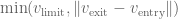

To come up with more robust solution of this problem, it needs to be both accurate for all ranges of motion and just as computationally efficient. After some thought, here’s what I came up with: First let’s assume that at a junction of two line segments, we only look at centripetal acceleration to simply things. In other words, we assume the tangential velocity is zero and the velocity through it is constant. At the junction, let’s place a circle with a radius 


This circular segment creates a virtual deviation from the path 
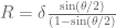
An efficient computation of the circle radius is as follows. If you do the geometry in terms of the known variables, you get: 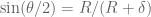

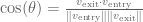
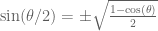
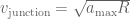
Now just plug and chug these equations into the centripetal acceleration equation above. You’ll see that there are only two sqrt() computations per junction and absolutely no trig sin() or acos(). To then find the absolute maximum velocity through the junction, just apply: 
This approach is both computationally efficient and accounts for the junction nonlinearities of how sharp the angle is between line segments and how fast the CNC can travel through each junction. Meaning that for right angles or reversing, the computed maximum junction speed is at or near zero. For nearly straight junctions, the computed maximum junction speed is near or at the nominal feedrates, which mean it can fly through the junction without worrying about exceeding the acceleration limits. This has been successfully tested on my machine and by several very helpful users, who have reported that they can crank up the feed speeds of their machines and it runs much smoother through complex paths. Lastly, keep in mind this method is a virtual path deviation that is only used for robustly computing the junction speed and does not actually mean there is a physical path deviation in your CNC machine.
